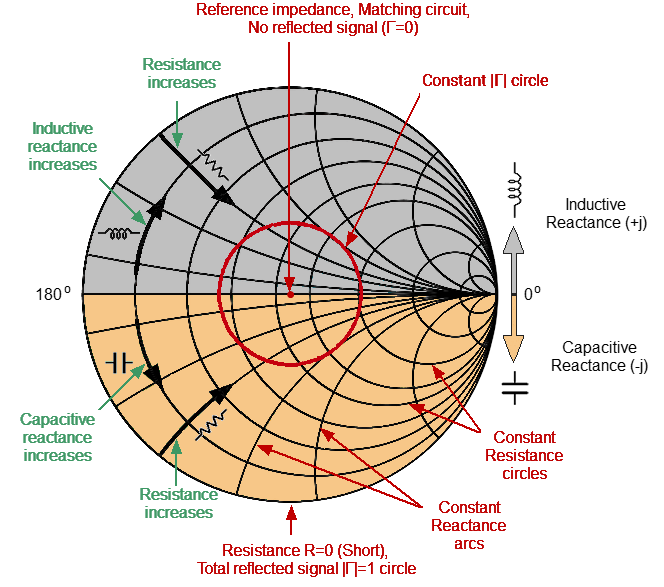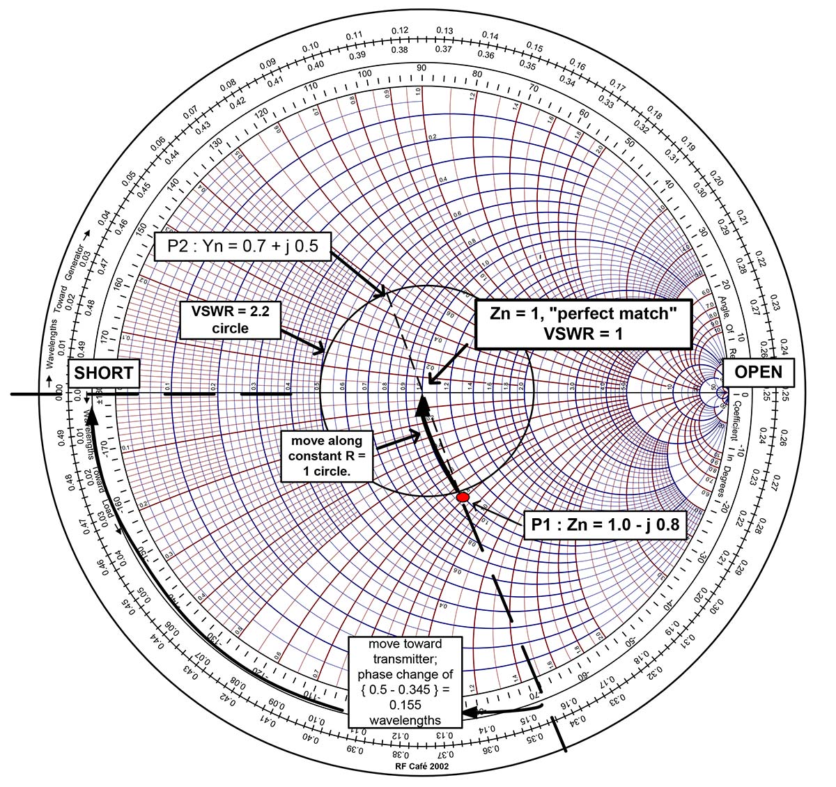

Choose if to show or not the label of every result. The Smith chart is made up of multiple circles, and segments of circles arranged in a way to plot impedance values in the form of R jX (Fig. a short circuit, or a termination resistance equal to the characteristic impedance Z. Choose the color and if to show or not every result. You can also insert a custom circle and a segment in the input and in the output plane, defining its center and radius in a textfield. Other results: obtained results (Ga, Gp, Gt, NF) and stability results (D, K, kind of stability).

Results representable on the smith chart: input/output stability circles, equiGa, Gp, Gt, NF circles, reflection coefficients towards load and source and optimum power coefficients. You will see the results appear on the chart while you are inserting data. Insert: scattering parameters, specifications (Ga, Gp, Gt, NF), noise data (gamma s optimum noise, minimum NF, rn) and the input/output reflection coefficients. Then use the padlock button to disable interaction of gestures with circles.
#Smith chart impedance series#
Sanfoundry Global Education & Learning Series Microwave Engineering. c) Admittance chart cannot be obtained from the impedance chart anyway. Insert circles by hand modify the radius dragging a circle to keep the center in place, or press to translate them and modify the radius keeping the opposite side in place. To get an admittance chart from an impedance chart: a) Smith chart has to be rotated by 90. AAplot can either plot the measure value as impedance components (resistance. Tap the chart with the finger or Apple Pencil to show the coordinates in algebraic notation, then tap on the pointer button to show magnitude and phase of that location, and the corresponding impedance. A Smith Chart maps the entire right half of a complex plane into a finite circle. This tool is javascript so it works on Windows, Mac, IOS, Android.
#Smith chart impedance generator#
Use a ruler and drag it with the finger or Apple Pencil to obtain the wavelength toward generator of a point on the chart, instantly. This free online interactive Smith chart tool is a calculator which can help you design matching networks and obtain maximum power transfer between your source and load. Switch easily between input and output plane. Easily show the parameters of the transmission lines in high-frequency circuit applications. Circles and contours for stability, noise figure, gain, VSWR and Q. Free settable normalisation impedance for the Smith chart. Create multiple Smith Charts and name them. Matching ladder networks with capacitors, inductors, resistors, serie and parallel RLC, transformers, serie lines and open or shorted stubs. Impedance and admittance charts are used to calculate the component values needed for device in different parts of the impedance matching circuit. With hand circles, ruler and point reader this chart can easily replace a physical one, making its use much faster. If True, default values are used.A great experience of the Smith chart. Only changesĭraw_vswr ( list of numbers, Boolean or None, optional) – draw VSWR circles. Ref_imm ( number, optional) – Reference immittance for center of Smith chart. Not used if draw_labels = True.Īx ( or None, optional) – existing axes to draw smith chart on. ’yz’ : lines of constant admittance stronger than impedanceĭraw_labels ( Boolean, optional) – annotate real and imaginary parts of impedance on theīorder ( Boolean, optional.) – draw a rectangular border with axis ticks, around the perimeter

’zy’ : lines of constant impedance stronger than admittance SmithR ( number, optional) – radius of smith chart. The Smith chart is formed from a rectilinear impedance plane by. Scattering parameters, noise figure circles, etc. note On circular diagrams (Polar and Smith chart), any point of the trace can be defined. The WTG scale is labeled in terms of the transmission-line length in wavelengths (not electrical degrees). Parameters including impedances, admittances, reflection coefficients, To graphically find the input reflection coefficient or input impedance, we first identify the scale WAVELENGTHS TOWARD GENERATOR (WTG) on the Smith Chart’s outer perimeter see green oval in Figure 1. It can be used to simultaneously display multiple The Smith chart is used to assist in solving problems with transmission linesĪnd matching circuits. smith ( smithR = 1, chart_type = 'z', draw_labels = False, border = False, ax = None, ref_imm = 1.0, draw_vswr = None ) 


 0 kommentar(er)
